Redundancy for power substations and other critical infrastructure networks
High availability is crucial for automation systems. As information and communication technologies become ever more important,
high availability concepts have also to be applied to these. Ethernet is gaining market share for many critical projects.

THE FAILURE of certain components in factory automation, process industry or substation automation applications, which never can be totally avoided, have to be handled in a way that minimises the influence to the system. High availability can be achieved by using complete system redundancy – every device is doubled using duplicated SCADA systems, servers, controllers, sensors and actuators, as well as duplicated networks.
As every component is available two times independently, any random failure should not influence the system, as long as the second system continues to run properly. However, complete system redundancy is the most expensive way of high availability.
Network media redundancy is a concept that concentrates on communication network redundancy. A communication network is designed in such a way that it can compensate for the breakdown of a communication link through a standby and failover mechanism to a secondary network connection.
Media redundancy describes concepts that compensate for breakdowns in a distributed network system, including network media (e.g. cables), network switches and even network interfaces.
No alternative paths
A basic requirement for every Ethernet network is the avoidance of any loops. Every loop would result in data frames circulating forever, so flooding the network. For this reason, there must not be any alternative paths to any device; at any one time only one single way to any end device is allowed.
For media redundancy, however, there MUST be alternative paths available. To solve this conflict, a redundancy control protocol comes into place. Such a protocol has to make sure that there is always only one single logical link to any end device, even when there are multiple physical links. The protocol has to guarantee that at any time only one of the links is used to transfer data, while all other links have to be in stand by mode.
One approach, which has been used in Industrial Ethernet applications as well as in standard IT applications for many years, is based on monitoring the communication paths, detecting any communication failures, and switching over to an alternative path if any failure is detected. This approach always results in a certain communication downtime because the failure has first to be detected, then the network has to switch to the alternative path, and has then to re-establish the communication. There are several protocols on the market that use this approach, and they differ greatly in failover time and supported topology.
STP and RSTP
One of the first protocols for redundancy control was the Spanning Tree Protocol (STP). Defined in the early 1990s, and used for many years in industrial and IT applications, this protocol shows some 10s for failover time, but handles different topology types, including meshed networks. However, STP has limitations in the number of hops (number of switches between sender and receiver).
The Rapid Spanning Tree Protocol (RSTP) generally replaced STP. This is an improved version of STP and was defined from IEEE 802.1 group in 1998. RSTP implementations work well in different topologies, support a larger number of switches, and improve failover time in the range of around one second. However, RSTP still does not guarantee deterministic failover behaviour. Reaction depends heavily on the location of the failure and on the individual implementation. For this reason, there have been attempts to optimise RSTP by restricting its use on ring networks, and by using special pre-defined parameters. With this optimisation, failover times in the range of 100ms or lower have been demonstrated.
The spanning tree protocol, as the name suggests, creates a spanning tree of connections between Ethernet switches, and disables all links that are not part of the tree (Fig. 1). This results in a single active path between any end devices. The protocol uses so called Bridge Protocol Data Units (BPDUs) to communicate between the switches, to define a ‘root bridge’ as the root of the tree, and to define and set up the optimal paths in the network. In case of any alteration to the network, those changes are announced to the network by using Topology Change Notification BPDUs. These result in a re-calculation of the spanning tree, activation of the corresponding stand-by paths and re-established communication.
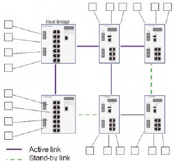
Fig.1. The rapid spanning tree protocol. This creates a spanning tree of connections between Ethernet switches, and disables all links that are not part of the tree.
When the topology is restricted to a ring, RSTP fault recovery time can be deterministic and can be calculated, provided that the RSTP timing performance characteristics of the switches are known.
Media Redundancy Protocol
A protocol that addresses industrial applications especially is the Media Redundancy Protocol (MRP). This is defined in IEC 62439, the industry standard for high availability networks. MRP is defined exclusively for ring networks, but guarantees deterministic failover behaviour. Depending on the selected parameter set, the worst-case failover time can be 500ms, 200ms, 30ms or 10ms – even in networks with 50 or more switches in a ring.
With MRP, one of the nodes has the role of a Media Redundancy Manager (MRM). The MRM supervises and controls the ring topology in order to react to network faults. The MRM does this by sending frames on one ring port into the ring and receiving them from the ring over its other ring port, and vice-versa in the other direction.
All other nodes in the ring have the role of Media Redundancy Clients (MRC). A MRC reacts on received reconfiguration frames from the MRM and can detect and signal link changes on its ring ports (Fig. 2).
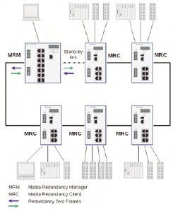
Fig. 2.MRP configuration. All other nodes in the ring have the role of Media Redundancy Clients (MRC). An MRC reacts on received reconfiguration frames from the MRM and can detect and signal link changes on its ring ports
Each MRP compliant node requires a switch element with two ring ports connected to the ring. Each node in the ring is able to detect the failure or recovery of an inter-switch link, or the failure or recovery of a neighbouring node.
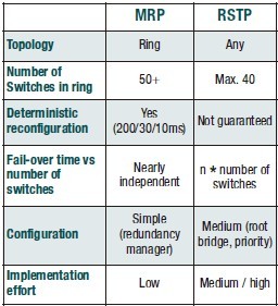
Comparing RSTP and MRP
If a ring topology is to be used, there is the option of using either RSTP or MRP. If deterministic behaviour is required, the protocol of choice should be MRP. MRP by definition reconfigures in case of a failure in a very deterministic way. Therefore, it is possible to guarantee a maximum re-configuration time, which in today’s implementations is 200ms (typically below 80ms). This fail-over time is nearly independent of the number of switches in the ring, because MRP control frames are transmitted as multicast frames through the ring, and so can be processed nearly simultaneously in all switches. In the meantime there are already switches available supporting the new fast parameter sets, with guaranteed failover times of 10 or 30ms, and typically around 5ms.
In contrast, RSTP control frames (BPDUs) are always transmitted hop-by-hop. This means that the frames have to be processed in each switch, and are then forwarded to the next switch. For this reason, the reconfiguration time increases with every additional switch. So even though – with a small number of switches – RSTP can achieve a very fast typical re-configuration time, in a large ring the times will sum to significant values.
It is also important to consider that with RSTP, the timing parameters are not specified as exactly as with MRP. So the actual fail-over time very much depends on the specific implementation in a particular product. RSTP performance, therefore, varies significantly from vendor to vendor, and even from product to product. In addition, the RSTP reaction time depends on other parameters; all of this makes an exact re-configuration time prediction nearly impossible in many topologies.
The position of the failure in the network, failure of a root bridge, or loss of Bridge Protocol Data Units (e.g. during high load situations) will influence the behaviour significantly so that, in certain cases, the actual re-configuration time will be much higher than the typical values.
Different approach – PRP and HSR
There are many redundancy protocols in place, mostly for ring redundancy, and most of them are proprietary implementations that can be used only in specific single vendor networks.
Considering the following: RSTP is successfully used in many applications in IT and industrial applications, fulfilling most requirements of real life networks; MRP is a redundancy control protocol with deterministic re-configuration as low as 10ms in its fastest version – and specified as an international IEC standard with many companies supporting it. Therefore, there is no longer any need to support non-standard redundancy schemes.
A totally different approach is based on networks with two independent active paths between any two devices. The sender uses two independent network interfaces, both sending the same data simultaneously. Here the redundancy control protocol has to guarantee that the destination uses only the first data packet, and discards the second one. If only one packet is being received, the receiver knows that a failure has occurred on the other path.
Comparison RSTP versus MRP
The Parallel Redundancy Protocol (PRP) and the High Availability Seamless Ring (HSR) use this principle. Both are specified in IEC 62439- 3. PRP uses two independent networks of any topology, while HSR is limited to a ring topology. The big advantage of both PRP and HSR is the zero reconfiguration time, which eliminates any downtime in case of a failure and thus guarantees the highest communication availability. This, of course, is only so as long as neither network exhibits a failure simultaneously (PRP), or as long as not more than one failure occurs at the same time (HSR).
The PRP protocol has to be implemented in the end devices, while the switches in the networks are standard devices, and do not have to ‘know’ anything about PRP. An end device with PRP functionality is a Double Attached Node (DAN), having one connection to each of the two independent networks. Those two networks can have identical topologies, or they can differ in topology or performance.
A standard device with a single network interface (Single Attached Node, SAN) can be attached directly to one network only. In such a case, this specific device has no redundant path available in case of a network failure. Alternatively, a SAN can be connected to a Redundancy Box (‘RedBox’), which then connects one or several SANs to both networks. SANs do not need to be aware of PRP; they can be off-the-shelf devices.
In many applications, only critical devices need a dual attachment, while non-critical devices are connected as SANs, with or without the use of a redundancy box.
A DAN implementation has to manage the redundancy and has to handle duplicates.
When receiving a frame from its upper layers, the PRP implementation sends the frame through both its ports at the same time. The two frames transit through the two independent networks, typically with different delays. At the destination node, the PRP implementation forwards the first received frame to the node’s upper layer, and has to discard the second frame. Towards its upper layers it shows the same interface as the network adapter of a non-redundant adapter.
The redundancy box implements the PRP for all the SANs attached to it, and it works as a kind of redundancy proxy for those devices. Fig. 3 shows a configuration using PRP.
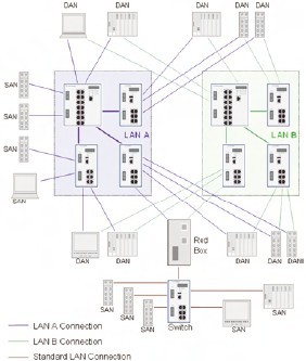
Fig. 3. A configuration using PRP. The redundancy box implements the PRP for all the SANs attached to it, and it works as a kind of redundancy proxy for those devices
HSR is a special version of PRP. HSR is limited to ring topologies and uses DANs connected to each other without dedicated Ethernet switches. Compared with other approaches, the available network bandwidth is halved because two frames of every data packet are transmitted over the ring. Nodes within the ring are restricted to be HSR-capable switching end nodes.
An HSR node receiving a unicast frame, with its own MAC address as destination, will pass this frame to its application layers and will discard the duplicate. A multicast or broadcast frame from the ring will be forwarded to the other ring port, and the first frame might be copied to its upper layers depending on its forwarding rules. After the frame crosses the complete ring, the sender has to remove the packet from the ring to avoid packet circulation.
General purpose nodes (SANs) cannot be attached directly to the ring, but require a Redundancy Box. Fig. 4 shows a typical HSR configuration.
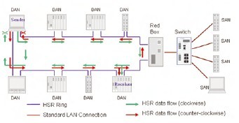
Fig. 4. A typical HSR configuration. General purpose nodes (SANs) cannot be attached directly to the ring, but require a Redundancy Box (‘Red Box’)
And finally�
Typically, in today’s automation applications, RSTP and MRP are the redundancy control protocols used. These protocols cover most of today’s requirements, but there are applications that cannot tolerate a failure of even a few milliseconds. For those applications, PRP or HSR will be the protocols of choice. However, both PRP and HSR are very new. While PRP is already in use in some applications, HSR has just been defined and first products are expected to be available within the next months.
Certain industrial Ethernet switches already have RSTP and MRP redundancy control protocols implemented, and have proved their benefit in thousands of applications. Future products will also support the new ‘zero reconfiguration’ redundancy protocols PRP and HSR.
Author: Andreas Dreher
Matching products for redundancy, remote control and Cyber Security:
MSP Modular DIN rail switch serie
Netmodule remote communication
Logger computer 19″ for local positioning at station for non critical logs and data


